DXF Countertop Layout — From Slab Photo to CNC-Ready File
Export true-scale DXF files that your CNC reads without modification. No scaling. No rotation. No guesswork.
SlabKast generates DXF files where piece outlines are positioned exactly as they appear on the calibrated slab image. The calibration targets on the physical slab become the coordinate reference. Zero your CNC to the targets, import the DXF, and cut. The pieces land exactly where the client approved them.
What CNC operators need from layout software
If you run a CNC bridge saw, waterjet, or router in a stone fabrication shop, you know the frustration. Someone hands you a piece of paper with wax pencil marks, or a screenshot of a CAD file with dimensions scribbled in the margin, or a DXF that was drawn at an arbitrary scale and needs manual adjustment before you can cut. Every time you re-enter coordinates, re-scale a file, or re-interpret someone else's markup, you introduce error.
CNC operators do not need fancy graphics or marketing features. They need four things from layout software, and if any of these are missing, the DXF is useless at the machine.
True-scale DXF in millimeters
No scaling factor. No “multiply by 25.4 to convert from inches.” The file is at true scale. One unit in the DXF equals one millimeter on the slab.
Piece outlines positioned on the slab
Not centered at origin. Not floating in CAD space. Pieces are positioned exactly where they will be cut on the physical slab.
Reference points matching physical targets
The DXF coordinate system is anchored to physical markers on the slab. When you zero the CNC to those markers, the DXF and the slab are aligned.
No manual adjustment needed
Import the file. Set toolpath. Zero the machine. Cut. If the DXF requires manual repositioning, rotation, or scaling, it defeats the purpose of digital slab layout.
How SlabKast DXF export works
The DXF export in SlabKast is not a generic “save as DXF” function. It is specifically designed for the slab-to-CNC workflow, and the coordinate system is built around physical calibration targets that exist on both the digital layout and the physical slab.
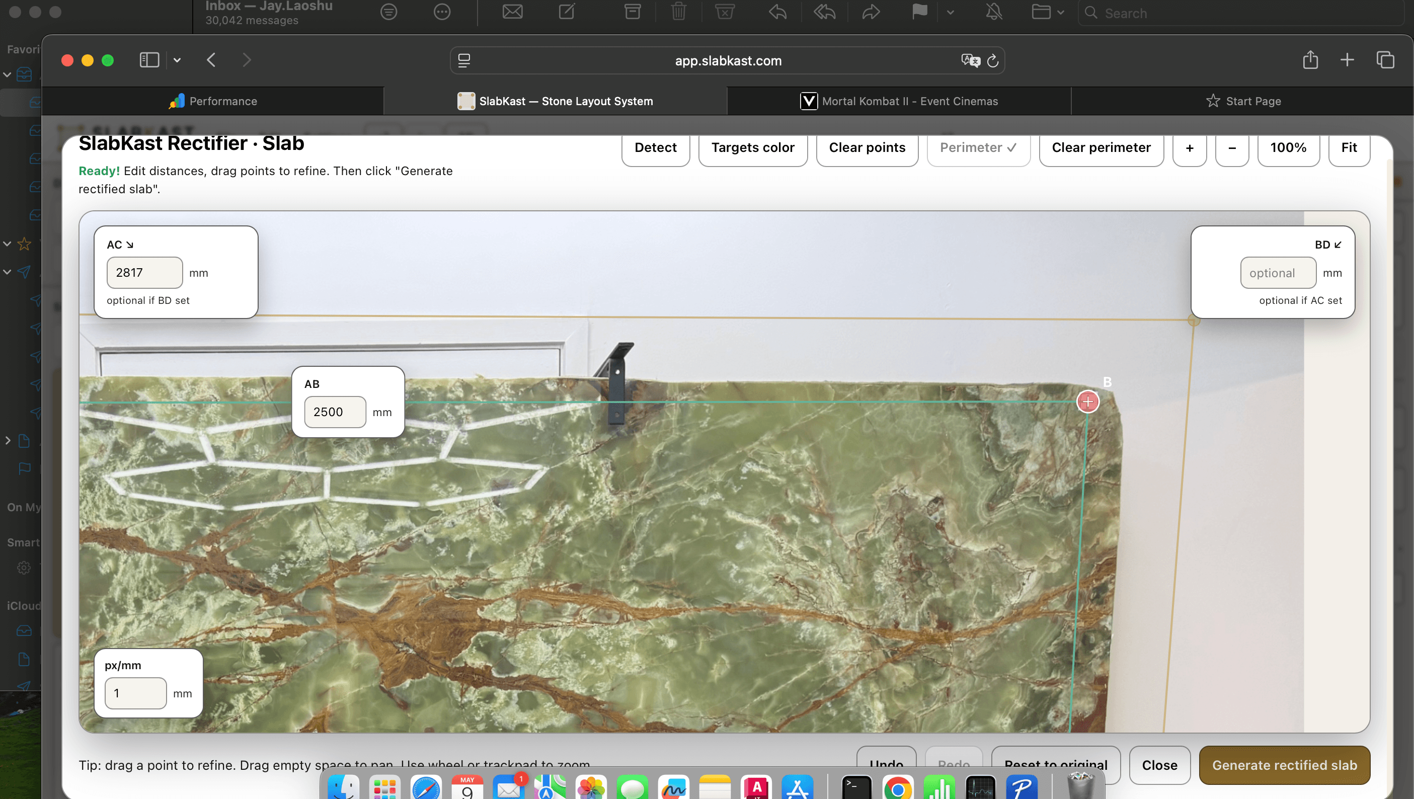
When you photograph a slab in SlabKast, you place four calibration targets on the slab surface. You measure the distances between these targets with a tape measure and enter those measurements into the software. SlabKast uses these measurements to correct the perspective distortion in your phone photo and create a dimensionally accurate slab image.
The calibration targets become the coordinate backbone of the entire workflow. In the digital layout, target positions are known in pixel coordinates. After calibration, those pixel coordinates map to real-world positions in millimeters. When you place template pieces on the calibrated slab image, their positions are recorded in the same coordinate system.
When you export the DXF, SlabKast writes the piece outlines at their real-world positions using target 1 as the coordinate origin (0,0). The DXF contains: piece outlines as closed polylines at true scale, target positions as reference points, and piece labels as text entities. Everything is in millimeters.
At the CNC machine, the operator places the physical slab on the table. They locate target 1 on the slab — the same target that was marked as position 1 during photography. They touch off the CNC spindle or laser pointer to that target and set it as the machine origin (X0, Y0). The DXF coordinate system and the physical slab are now aligned.
The operator can verify alignment by jogging the machine to the DXF coordinates of targets 2, 3, and 4 and checking that the machine position matches the physical target positions on the slab. If all targets align within 1-2mm, the setup is confirmed and cutting can begin. Read the complete phone photo to CNC workflow for a step-by-step walkthrough.
The target-to-CNC accuracy chain
Accuracy in DXF countertop layout is not a single number. It is a chain, and the weakest link determines the final result. Every step matters. Here is the complete chain from slab photograph to finished cut.
Photography
Capture a clear, well-lit photo of the slab with all four calibration targets visible. Shooting angle, lighting, and image sharpness all affect the quality of the calibrated image. Shoot from directly above when possible. Avoid harsh shadows that obscure target positions.
Target measurement
Measure distances between calibration targets with a steel tape measure or laser distance meter. This is the most critical step. A 5mm measurement error on a 3-meter slab creates a proportional error across the entire layout. Measure twice. Use the same reference point (center of target) consistently.
Perspective rectification
SlabKast uses the known target positions to mathematically correct the perspective distortion in your phone photo. The algorithm transforms the angled photograph into an orthographic (top-down) view at true scale. This step is fully automated — accuracy depends on the quality of input measurements.
Layout planning
Template pieces are positioned on the calibrated slab image. Piece positions are recorded in the real-world coordinate system established by the targets. What you see on screen is what will be cut.
DXF export
Piece outlines are written to the DXF file at their real-world coordinates. The file uses millimeters as the unit. Target positions are included as reference points. No transformation or scaling occurs during export — the DXF is a direct expression of the calibrated layout.
CNC zeroing
The operator zeros the CNC machine to target 1 on the physical slab. This is the second most critical step. A 2mm error in zeroing creates a 2mm offset across every piece. Use a pointed tool or laser pointer for precise touch-off. Verify by checking targets 2, 3, and 4.
Cut
The CNC follows the DXF toolpath and cuts the pieces. The machine's own positional accuracy (typically 0.1-0.3mm for a well-maintained bridge saw) adds a negligible contribution to the overall error budget. The dominant error sources are target measurement and CNC zeroing.
With careful measurement and zeroing, the end-to-end accuracy of the SlabKast DXF workflow is 1-2mm across the full slab. For context: a standard bridge saw blade kerf is 3-4mm, and edge polishing removes another 1-2mm of material. A 1-2mm positional accuracy is well within the practical tolerance for countertop fabrication.
The accuracy is more than sufficient for the primary purpose of DXF countertop layout: ensuring that pieces are cut from the correct area of the slab, that vein alignment matches the approved countertop layout, and that seams fall where the client expected.
DXF file specifications
Here is exactly what the SlabKast DXF file contains, so your CNC operator knows what to expect before they open it.
The file is intentionally simple. No hatches, no dimension annotations, no blocks, no splines. Just clean polylines that any CNC controller can interpret without issue. If your CAM software reads DXF, it reads SlabKast exports. We have tested with Alphacam, FlexiCAM, Park Industries controllers, BACA Systems, Northwood, Intermac, Breton, and GMM. Compatibility is universal because we use the simplest, most widely supported DXF entities.
Common DXF mistakes to avoid
The SlabKast DXF is designed to be import-and-cut. But there are a few things that CNC operators do out of habit with other DXF files that will cause problems with a calibrated slab layout export.
Scaling the file
This is the most common mistake. Many CNC operators are accustomed to scaling imported DXF files because the files they receive from designers and architects are often at arbitrary scales. SlabKast DXF files are already at true scale in millimeters. If your CAM software asks for a scale factor on import, enter 1.0. If it asks for units, select millimeters.
Scaling a SlabKast DXF will move every piece out of position relative to the calibration targets. The pieces will no longer align with the slab, and the cut will not match the approved layout.
Incorrect CNC zero point
The DXF uses target 1 as the coordinate origin. If you zero your CNC to the corner of the slab instead of target 1, every piece position will be offset by the distance between the slab corner and target 1. This offset might be 50-100mm — enough to ruin the layout.
Always zero to target 1. Always verify by checking that the machine coordinates at targets 2, 3, and 4 match the DXF reference points. This takes 30 seconds and prevents a $4,000 mistake.
Not verifying target alignment before cutting
Zeroing to target 1 is necessary but not sufficient. The slab might be rotated on the table compared to the photograph orientation. If you only check target 1, the origin is correct but the rotation could be off by several degrees — enough to shift a piece 5-10mm at the far end of the slab.
After zeroing to target 1, jog the machine to the DXF coordinates of targets 2, 3, and 4. Verify that each one aligns with the physical target on the slab. If any target is off by more than 2mm, recheck your zero point and slab orientation.
Wrong tool offset settings
The DXF provides piece outlines — the finished edge of each piece. Your CAM software needs to apply the correct tool offset (blade kerf compensation) so the CNC cuts on the waste side of the line, not through the center of it. This is standard CNC practice, but it is worth mentioning because an incorrect tool offset shifts every edge by 1.5-2mm.
Set your tool offset based on your actual blade width. For a standard diamond bridge saw blade, the kerf is typically 3.2-3.8mm. Your CAM software should offset the toolpath by half the kerf to the waste side.
From DXF to finished countertop
Here is the complete CNC workflow from the moment you receive the SlabKast DXF to the moment the last piece comes off the saw. This is the process your operator follows for every job.
Import the DXF into your CAM software
Open the SlabKast DXF in Alphacam, FlexiCAM, or your preferred CAM application. Set the import unit to millimeters. Do not scale. You should see piece outlines positioned in the first quadrant (positive X and Y), with target reference points visible. The geometry should match what you saw in the SlabKast layout.
Set toolpath parameters
Define your cutting parameters: blade type, RPM, feed rate, depth of cut, lead-in and lead-out moves, and tool offset (kerf compensation). These settings are specific to your machine and blade — they are not included in the DXF because they vary by shop. Apply the toolpath to each piece outline.
Place the slab and zero the machine
Position the slab on the CNC table. Locate target 1 on the physical slab. Touch off the spindle or laser pointer to the center of target 1 and set X0, Y0. If your machine uses a Z reference, touch off to the slab surface and set Z0.
Verify alignment at targets 2, 3, and 4
Jog the machine to the DXF coordinates of target 2. Check that the spindle or laser pointer aligns with the physical target on the slab. Repeat for targets 3 and 4. All targets should be within 1-2mm. If any target is off by more than 2mm, recheck your zero point and slab orientation on the table.
Cut
Run the toolpath. The CNC cuts each piece at the exact position where it appeared in the client-approved layout. The veins, seams, and piece orientations match what the client saw on their phone. No surprises at installation.
The entire CNC setup — from importing the DXF to verifying target alignment — takes 5-10 minutes. Compare that to the old workflow: interpreting wax pencil marks, manually entering coordinates, second-guessing piece positions, and hoping the finished result matches what someone described over the phone.
For the complete upstream workflow — from photographing the slab to creating the layout to getting client approval — read the phone photo to CNC workflow guide. For layout planning details, see our digital slab layout overview. For a hands-on walkthrough, follow the step-by-step tutorial.
Questions CNC operators ask about DXF workflow
Does the SlabKast DXF need to be scaled before importing into my CNC software?
No. The DXF exports at true scale in millimeters. If your CNC software is set to millimeters, the file imports at the correct size with no manual scaling needed. If your CAM software defaults to inches, set the import unit to millimeters before loading the file. Never scale the DXF manually — it is already dimensionally accurate based on the calibrated slab measurements.
What CNC machines are compatible with SlabKast DXF files?
Any CNC saw, bridge saw, waterjet, or router that accepts standard DXF input. This includes machines from Park Industries (Yukon, Titan, Fusion), BACA Systems (Robo SawJet, RoboJet), Northwood, Intermac (Master, Primus), Breton, GMM, Denver, Prussiani, and others. If your machine reads DXF, it reads SlabKast exports. We use standard polyline entities — no proprietary layers, blocks, or custom objects.
How do I zero my CNC to the calibration targets on the slab?
The DXF file includes the calibration target positions as reference points. Place the slab on your CNC table in the same orientation as the photograph. Identify target 1 on the physical slab (the target you marked as position 1 during photography). Touch off your CNC spindle or laser pointer to that target and set it as the origin (X0, Y0). Verify alignment by checking targets 2, 3, and 4 — the machine coordinates should match the target positions in the DXF within 1-2mm.
What entities does the DXF file contain?
The DXF contains piece outlines as closed polylines, calibration target positions as point entities, and piece labels as text entities. There are no hatches, dimensions, or complex blocks that might confuse older CNC controllers. The file uses a flat structure — all entities are on layer 0 unless you configure custom layer mapping in SlabKast settings.
Can I edit the DXF file before sending it to the CNC?
Yes. The DXF is a standard file that opens in any CAD or CAM software. You can add toolpath parameters, adjust tool offsets, add lead-in and lead-out moves, and define cutting sequence order in your CAM software. What you should not do is scale or reposition the piece outlines — those are already at true scale and correctly positioned relative to the calibration targets.
What accuracy can I expect from the DXF cutting positions?
The accuracy of the DXF positions depends on the accuracy chain: target measurement, photo calibration, and CNC zeroing. With careful target measurement (using a steel tape measure or laser measure) and proper CNC zeroing to the physical targets, most users achieve 1-2mm positional accuracy across the full slab. This is well within the tolerance needed for piece placement on the slab — your bridge saw blade kerf is typically 3-4mm, and your edge polishing removes another 1-2mm.
Generate your first CNC-ready DXF from a slab photo
7-day free trial. Photograph a slab, build a layout, export the DXF, and cut. See how a calibrated DXF workflow eliminates coordinate re-entry and cutting errors.
New to digital layout? Start with our digital slab layout overview →