DXF Countertop Layout: From Approved Layout to CNC Cut File
Export the approved layout as a true-scale DXF. Load it into your CNC. Zero to the targets. Cut.
The layout your client approved on their phone is the same layout your CNC operator loads at the saw. No redrawing. No coordinate re-entry. No interpretation. The DXF contains the exact piece outlines, at the exact positions, in the exact coordinate system that maps to the physical calibration targets on the slab.
The layout-to-cut gap
In most stone fabrication shops, the layout happens in one system and the CNC program is created in another. The salesperson or project manager decides where pieces go on the slab — maybe using a photo markup, maybe using a separate layout tool, maybe using wax pencil on the physical stone. Then that layout has to be translated into something the CNC can read.
This is where mistakes happen. Someone redraws the piece outlines in AutoCAD or directly in the CAM software. Coordinates get rounded. A piece gets flipped. A seam location shifts by 20mm because the operator measured from the slab edge instead of the reference point used in the layout. The CNC cuts exactly what it is told — but what it is told no longer matches what the client approved.
The layout-to-cut gap is not a technology problem. Every shop has a CNC that reads DXF. Every shop has someone who can draw piece outlines. The problem is that the layout and the cut file are created independently. They share no data. They share no coordinate system. The connection between “what the client approved” and “what the CNC cuts” is a human being re-entering information.
SlabKast closes this gap. The layout is created on a calibrated slab photograph. The client approves that layout. The DXF is exported from that same layout — same pieces, same positions, same coordinate system. No redrawing. No re-entry. No gap. The approved layout IS the cut file. The only human steps at the CNC are: import the DXF, zero to the targets, verify alignment, and cut.
DXF export specifications
Here is exactly what the SlabKast DXF contains. No ambiguity. Your CNC operator knows what to expect before opening the file.
The file is intentionally simple. Closed polylines, points, and text — nothing else. No hatches, no dimension annotations, no splines, no blocks. This is deliberate. The simpler the DXF, the more universally compatible it is. Legacy bridge saw controllers that choke on complex DXF files handle SlabKast exports without issue because the entities are the most basic, most widely supported types in the DXF specification.
Compatible with: Alphacam, FlexiCAM, Park Industries controllers (Yukon, Titan, Fusion), BACA Systems, Northwood, Intermac, Breton, GMM, Denver, Prussiani, and any waterjet or CNC router software that imports DXF. If your machine reads DXF, it reads SlabKast exports.
The accuracy chain
DXF accuracy is not a single number. It is a chain of steps, and the output accuracy depends on the weakest link. Every step from the slab photo to the CNC cut contributes to the final positional accuracy of each piece. Here is the complete chain.
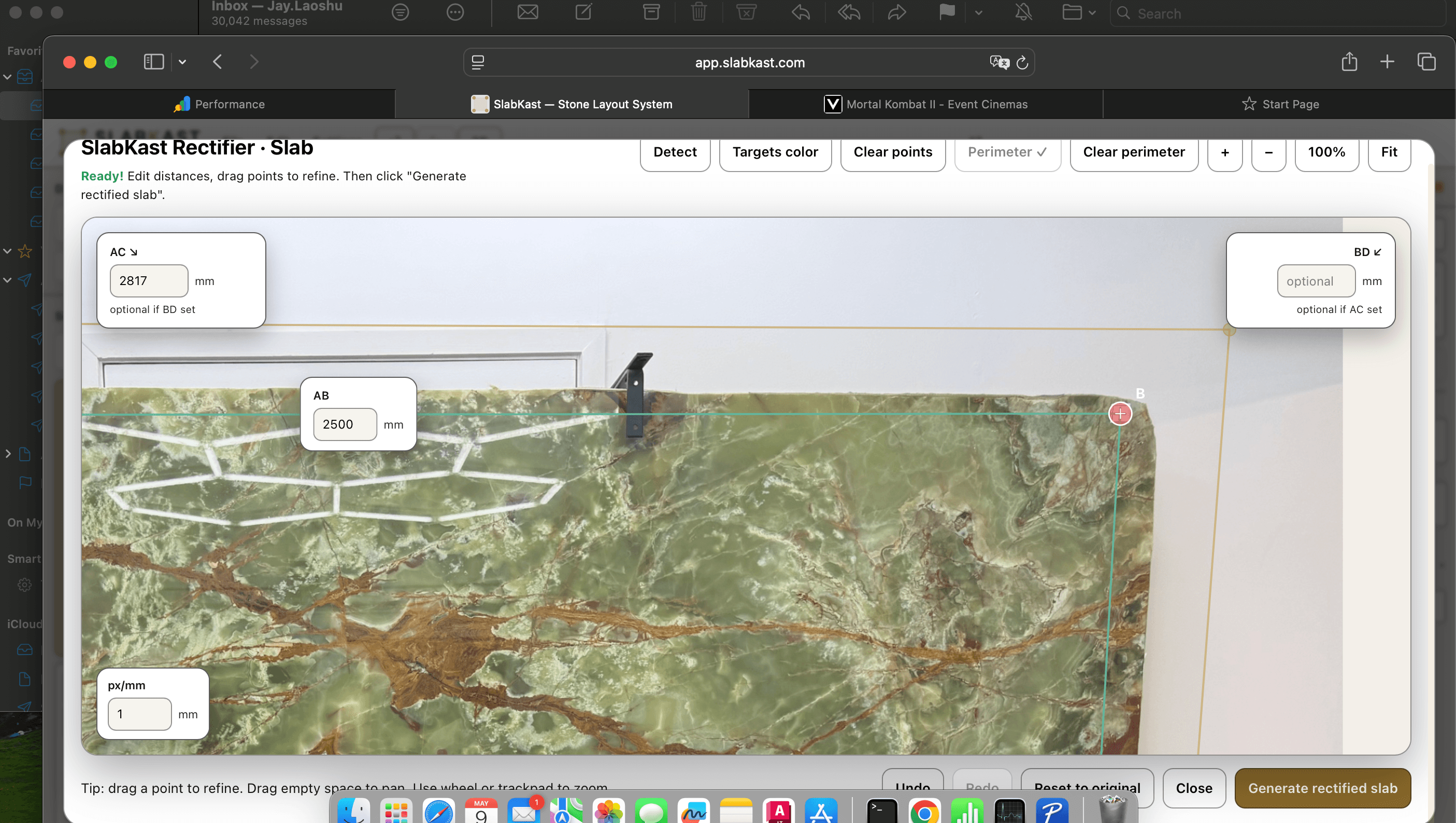
Photo
Photograph the slab with all four calibration targets visible. A clear, well-lit shot from above gives the best calibration result. Angle does not need to be perfectly perpendicular — the rectification algorithm corrects perspective — but less angle correction means less distortion in the final image.
Target measurement
Measure distances between calibration targets with a steel tape or laser measure. This is the single most important step for accuracy. A 5mm measurement error propagates proportionally across the entire slab. Measure from target center to target center. Measure twice.
Rectification
SlabKast uses the target positions and measured distances to compute a perspective correction. The phone photo is transformed into a true top-down view at real-world scale. This step is fully automatic — its accuracy depends entirely on the input measurements.
Layout
Template pieces are placed on the calibrated slab image. Their positions are recorded in the same coordinate system defined by the targets. What you see on screen IS the real-world position, in millimeters, relative to target 1.
DXF export
Piece outlines are written to the DXF at their calibrated real-world positions. No transformation occurs during export. The DXF is a direct expression of the layout coordinates. The origin is target 1.
CNC zero
The operator touches off to target 1 on the physical slab and sets X0, Y0. This is the second most critical step. A 2mm zeroing error creates a 2mm offset on every piece. Use a pointed tool or laser pointer for precision. Verify by checking targets 2, 3, and 4.
Cut
The CNC follows the DXF geometry. Machine positional accuracy (typically 0.1-0.3mm for a well-maintained bridge saw) adds negligible error. The dominant contributors are target measurement and CNC zeroing.
The output accuracy matches the input accuracy. Careful target measurement and precise CNC zeroing yield 1-2mm positional accuracy across the full slab. For context: a standard bridge saw blade kerf is 3-4mm, and edge polishing removes another 1-2mm of material. The DXF accuracy is well within fabrication tolerance for piece positioning on the slab.
The accuracy is more than sufficient for the primary goal: cutting pieces from the correct area of the slab so that the vein pattern, seam positions, and color distribution match what the client approved in the countertop visualization.
DXF + vein matching: the unique advantage
A standalone CAD drawing can define piece shapes and dimensions. But it cannot tell the CNC WHERE on the slab to cut each piece for the best vein alignment. The CAD operator draws pieces at arbitrary positions in model space and the CNC operator positions them on the slab by eye, using wax pencil marks or laser projections.
SlabKast is different because the layout is done on the real slab photograph. When the fabricator positions a piece, they see the actual veins running through it. They rotate it to align the vein direction. They position the seam where the vein pattern allows the smoothest transition. The DXF that exports from this layout carries those positions — not arbitrary CAD coordinates, but positions chosen for vein match on this specific slab.
This is the unique advantage of a DXF generated from a calibrated slab photo layout. The CNC cuts pieces positioned for the best vein alignment — something a standalone CAD drawing cannot achieve because a standalone CAD drawing does not know what the slab looks like.
For heavily veined materials — marble, quartzite, exotic granite — this is the difference between a countertop that looks intentionally designed and one that looks randomly assembled. Vein continuity at seams, consistent vein direction across pieces, and deliberate placement of character marks are all baked into the DXF because they were planned on the real stone.
Learn more about vein matching in SlabKast.
Common CNC integration questions
Practical, step-by-step answers for CNC operators integrating SlabKast DXF files into their daily workflow.
How do I import the DXF?
Open your CAM software (Alphacam, FlexiCAM, or your machine's built-in controller software). Use the standard DXF import function. When prompted for units, select millimeters. When prompted for scale factor, enter 1.0 or leave at default. The file should display piece outlines in the first quadrant with calibration target points visible. If the geometry appears at the wrong scale, check that your import unit is set to millimeters — not inches.
How do I zero the CNC to the slab?
Place the physical slab on your CNC table. Locate calibration target 1 — the target that was marked as position 1 during photography. Move your CNC spindle or laser pointer to the center of that target. Set X0, Y0 at that position. If your machine uses a Z reference, touch off to the slab surface and set Z0. Target 1 is now the shared origin between the DXF coordinate system and the physical slab.
How do I handle tool offset?
The DXF contains piece outlines — the finished edges of each piece. Your CAM software applies tool offset (kerf compensation) so the CNC blade cuts on the waste side of the line. For a standard diamond bridge saw blade with a 3.2-3.8mm kerf, set tool offset to half the kerf width (1.6-1.9mm) to the waste side. This is standard CNC practice — the DXF provides the geometry, your CAM handles the toolpath.
How do I verify alignment before cutting?
After zeroing to target 1, jog the machine to the DXF coordinates of target 2. The spindle or laser pointer should align with the physical target 2 on the slab within 1-2mm. Repeat for targets 3 and 4. If any target is off by more than 2mm, recheck your zero point. If all four targets align, your setup is confirmed. This verification takes 30-60 seconds and prevents a $3,000-$4,000 mistake.
From DXF to installed countertop
The DXF is the bridge between digital planning and physical fabrication. Here is the complete chain from export to installed countertop — every step, from the moment the DXF leaves SlabKast to the moment the last piece is set on the cabinet.
DXF export from approved layout
The client has approved the layout via the approval workflow. They have seen the pieces on the actual slab — in 2D visualization and optionally in 3D preview. The fabricator exports the DXF from the approved layout version. The file contains piece outlines at true scale in millimeters, positioned in the calibration target coordinate system.
CNC toolpath generation
The CNC operator imports the DXF into their CAM software. They assign cutting parameters: blade type, RPM, feed rate, depth, lead-in and lead-out, and tool offset. These parameters are shop-specific — they depend on the machine, the blade, and the material thickness. The CAM generates the toolpath from the DXF geometry.
Slab setup and CNC zeroing
The slab goes on the CNC table. The operator locates target 1, zeros the machine to it, and verifies alignment at targets 2, 3, and 4. Total setup time: 5-10 minutes including verification. Compare that to manually marking piece positions with wax pencil and a tape measure.
Cut
The CNC runs the toolpath. Each piece is cut at the exact position defined in the layout. Veins run through each piece as planned. Seams fall where the client saw them. Piece orientations match the approved visualization. The physical result matches the digital plan because they share the same data and the same coordinate system.
Edge polish and fabrication
Cut pieces go to edge polishing, cutout finishing (sink, cooktop, faucet holes), and final QC. Edge profiles are applied per the job specifications. The DXF defined the piece outlines — the finished edge position. Edge polishing removes material from the cut edge to reach the final profile.
Install
Pieces are transported to the job site and installed on the cabinets. Seams are joined with color-matched epoxy. The finished countertop matches the visualization the client approved — same veins, same seam positions, same stone. No surprises. No callbacks. No remakes.
The DXF is the critical link in this chain. It is the artifact that carries the approved layout into the physical world. Without it, there is a manual translation step between digital approval and physical cut — and that translation step is where most fabrication errors originate.
For the complete upstream workflow — from photographing the slab to building the layout — see how SlabKast works. For CNC-specific details on the existing root-level DXF page, see DXF countertop layout for CNC operators.
DXF countertop layout questions
What DXF version does SlabKast export?
SlabKast exports DXF files compatible with AutoCAD R2010 and later. The file uses standard LWPOLYLINE entities for piece outlines, POINT entities for calibration targets, and TEXT/MTEXT for piece labels. There are no proprietary objects, custom blocks, or version-specific features. Any CAM software that reads DXF — from current versions of Alphacam to legacy bridge saw controllers — can import the file without compatibility issues.
Do I need to scale the DXF when importing into my CNC software?
No. The DXF is exported at true scale in millimeters. One drawing unit equals one millimeter. Set your CAM software import unit to millimeters and import at 1:1 scale. Do not apply any scale factor. If your CAM defaults to inches, change the import unit setting to millimeters before loading the file — do not scale by 25.4. Manual scaling will shift every piece position relative to the calibration targets and break the alignment with the physical slab.
What CNC machines work with SlabKast DXF files?
Any CNC that accepts DXF input. This includes bridge saws from Park Industries (Yukon, Titan, Fusion), BACA Systems (Robo SawJet, RoboJet), Intermac (Master, Primus), Breton, GMM, Northwood, and Denver. It also includes waterjet systems, CNC routers, and standalone CAM software like Alphacam, FlexiCAM, and Mastercam. The DXF uses the most widely supported entity types — no special compatibility is needed.
How accurate is the DXF relative to the physical slab?
Positional accuracy depends on the full accuracy chain: target measurement, photo calibration, and CNC zeroing. With a steel tape or laser measure for target distances and careful CNC touch-off to the calibration targets, most users achieve 1-2mm positional accuracy across the entire slab. This is well within fabrication tolerance — your bridge saw blade kerf is 3-4mm and edge polishing removes another 1-2mm. The dominant error sources are manual measurement and CNC zeroing, not the software.
Can I open the DXF in AutoCAD or other CAD software for editing?
Yes. The DXF is a standard file that opens in AutoCAD, DraftSight, LibreCAD, or any CAD application. You can add dimensions, toolpath annotations, cutting sequence numbers, or any other production markup your shop needs. What you should not do is scale, rotate, or reposition the piece outlines — those are already at correct positions relative to the calibration targets. Add to the file, but do not modify the piece geometry or positions.
How does the DXF handle pieces that need to be cut from different slabs?
Each SlabKast layout is tied to one calibrated slab image. The DXF export contains only the pieces placed on that slab. If a job requires pieces from two slabs — for example, the main countertop run from slab A and the island from slab B — you create two layouts, one per slab, and export two DXF files. Each DXF uses its own calibration target coordinate system. At the CNC, you process each slab with its corresponding DXF.
Generate your first CNC-ready DXF. Free trial.
7-day free trial. Photograph a slab, build the layout, get client approval, export the DXF, and cut. See the full workflow from slab photo to CNC-ready file.
Want to see the visualization side? See real-slab countertop visualization →